Neonixie 6 Digit Clock Kit 2022, V2!


High Voltage Warning!
This board uses high voltage! 180 VDC is present on this board! Design current is limited and will likely, in most cases, not permanently harm you.. but it will definitely HURT you if improperly handled. If you do not have experience with high voltages, seek assistance. Operate this clock in a suitable enclosure and keep away from children/pets/etc.
What is this?
This is a reboot of an older nixie clock kit designed and sold in 2005, found Here
The clock is in production and can be purchased Here!
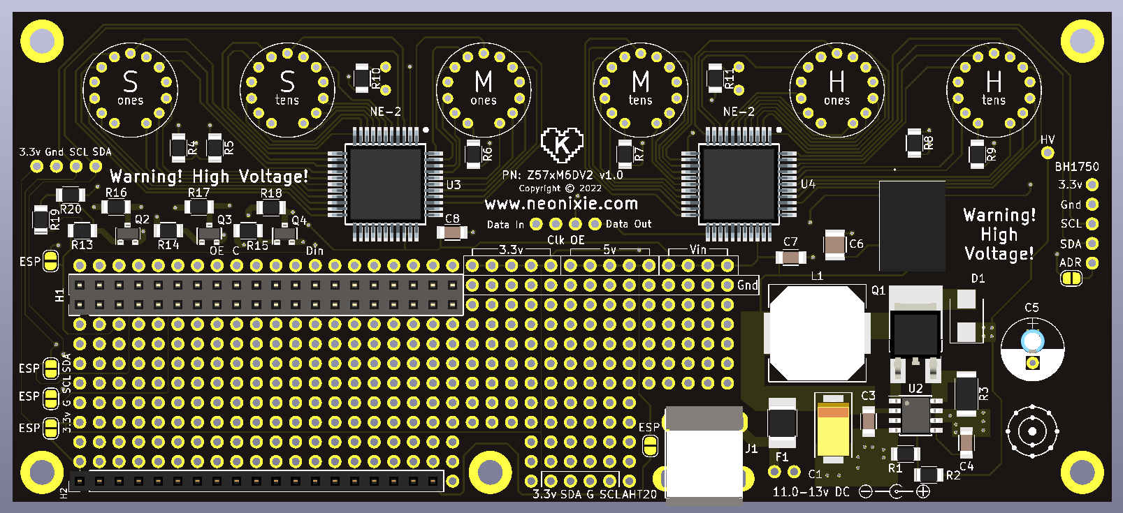
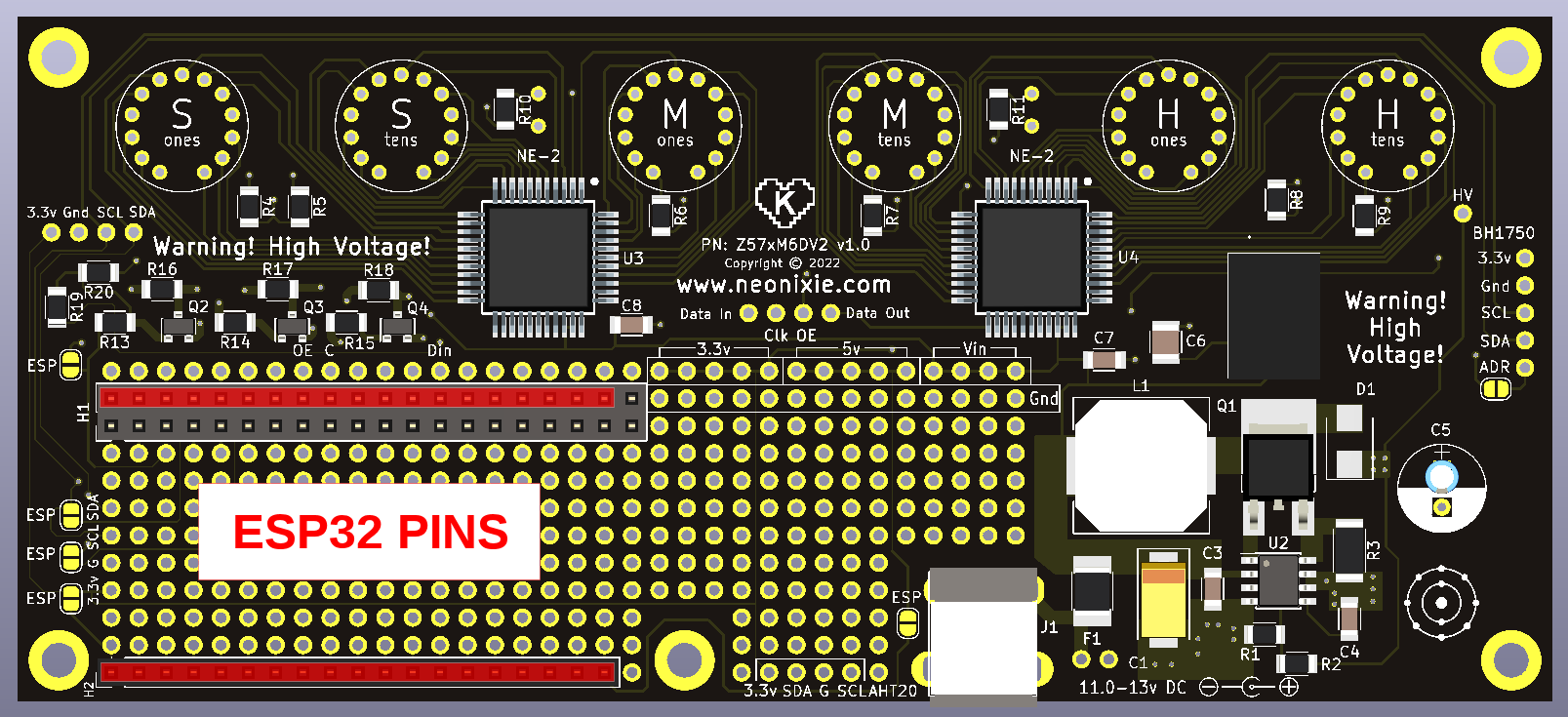
Throughout this page we will refer to the upper, lower, right and left sides of the board as is shown in the picture found HERE. Most of the silkscreen is also printed to be read in this orientation.
Table Of Contents
Circuit description
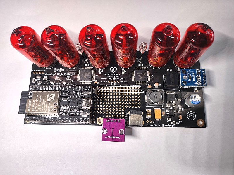
The clock contains 6 Z573M/Z574M nixie tubes driven by Supertex (now Microchip) HV5122(or HV5222) driver ICs. The HV5122 is a 32-Channel Serial To Parallel Converter IC and two are used. Two NE-2 bulbs are used as colon seperators and are driven by the HV5122 as well. A nominal 180V DC for the nixie tubes is provided by a MAX1771 boost converter IC achieving peak efficiencies of 86% (lower right hand side of board). 5v power to the board is provided by an efficient switching buck converter module capable of 1A output. The control of the clock is at the users discretion. The board is designed with pinouts for either a Raspberry Pi Zero W or various ESP32 modules (lower left hand corner of the board). The choice of Pi Zero W and ESP32 modules is primarily for ease of programming and expandability as well as the capability of having automatic internet based time setting and correction via NTP. Bluetooth connectivity and expansion modules will make possible the integration of a wide variety of sensors, such as temperature and light intensity. Through holes are provided thoughout the board for custom add on boards and circuits.
More details
- The DC jack is a standard 2.1mm(ID) x 5.5mm(OD) in size. Polarity is center positive. Improper polarity will damage the clock!
- Power usage with an ESP32 and tubes at high brightness is about 250ma at 12v, and about 300ma with a Pi Zero W.
- A REGULATED 12v DC adapter is recommended in the 500mA-750mA range. Voltage range can be 11-13 volts, but a REGULATED adapter is highly recomended. Do not exceed 13V on the input!
- Your DC adapter should have short, overvoltage and overcurrent protection. A 750mA self resetting polyfuse is provided on board for additional protection (F1).
- A logic level shifter converting the 3.3v of the controllers to 12v required by the HV5122 is composed of R13-R20, Q3, Q4 and Q5.
- Through-hole connections for alternate power input is provided just below F1 and is fused by F1.
- The entire 2 horizontal rows of header H1 is duplicated, one row above and one row below, for easy access to controller pins. The H2 header is duplicated above the header.
- Vin, Ground, 5.0v and 3.3v is provided by several points in the center of the PCB. Vin is fused by F1. 3.3v is provided by either the Pi or ESP controller and draw should be limited within the capacbilities of the controller used.
- All solid capacitor design. No electrolytic capcitors to dry out!
Back to Table of Contents
Assembly instructions
Throughout this page we will refer to the upper, lower, right and left sides of the board as is shown in the picture found HERE. Most of the silkscreen is also oriented to be read in this orientation.
All of the required surface mount components are already soldered on the board. The following needs to be soldered:
- J1, DC input jack
- U1, 5.0v regulator module, part number R-78E5.0-1.0, properly orient part with silkscreen outline on PCB.
- H1, 40 pin socket. BE SURE THIS IS IN THE CORRECT SPOT! Note, there is an "empty" row of pins above H1 that electrically duplicates the top row of pins and a duplicate of the bottom pins one row below as well. The location of where the H1 socket needs to be soldered is bordered in silkscreen as well (with a notch at pin 1). Once soldered a 40 pin socket is almost impossible to remove without damage to the board, make sure to position it properly!
- H2, 19 pin socket. BE SURE THIS IS IN THE CORRECT SPOT! This is soldered into the lower left hand corner of the board. Make sure to position it properly, again, this part is difficult to rework! This part can be omitted if using the clock with a Pi.
- The left side edge of the board contains 4 solderable jumpers marked ESP and one more near the DC input jack marked J1. Bridge all 5 solder jumpers if using an ESP and remove all jumpers if using a Pi. Incorrect jumper settings for the controller used may cause damage!
- Optional BH1750 Lux sensor: Solder the 5 pin socket on the right edge of the board marked "BH1750". Solder the 5 pin header to the BH1750 sensor board making sure to properly orient the longer pins so as the sensor is pointed towards the sky and not the PC board. You can optionally remote mount this sensor within the limitations of the power and I2C wiring.
- Optional AHT20+BMP280 Temperature/Humidity/Pressure sensor. Solder the 4 pin socket on the board marked AHT20 located near the DC input jack. The required 4 pins have a silkscreen border and are marked 3.3v, SDA, G and SCL. Solder the 4 pin header to the sensor with the long pins protruding from the component side of the sensor board. The sensor is designed to protrude from the back of the PCB with the sensor elements pointing DOWN. This mounting arrangement is meant to keep the sensor away from the PCB and out of the main enclosure to maintain sensor accuracy. The case design should accommodate this or optionally the sensor can be remote mounted within the limitations of the power and I2C wiring.
- Install the 6 nixie tubes, read the solder section below before final soldering! It is recommend to leave about 5-10mm of space between the bottom glass of the tubes and the board. It is recommended to NOT mount the tubes with the glass touching the PC board, as this makes them more prone to damage. Tubes are installed on the top, or component side of the board marked in silkscreen. The pins can be inserted into the board one by one by tilting the tube at an angle, this may take some practice if you have not done it before. An alternate and sometimes easier method of inserting the pins into the board can be acomplished by first trimming the tube pins in a spiral pattern as shown HERE. This makes it easier to insert each pin one at a time.
- SOLDER the nixie tubes / Alightment: The tubes should be aligned properly before final soldering. Alightment is easy working with two tubes at a time. Insert two adjacent tubes, for example the second ones and tens tube. Adjust the height off the board of one of the tubes and solder 'tack' the 12 o'clock pin on that tube, repeat on second tube duplicating the first tubes height. Next align the front to back 'tilt' to get the tube straight, tack the 5 or 7 o'clock position pin on that tube (there is no 6 o'clock position pin), repeat for second tube. Adjust the side to side tilt of the tubes, the gap between tubes is small and serves as a good side tilt indication, and tack the 9 or 3 o'clock position pin. This pair of tubes should now be properly aligned and should not move. You can cut all extra lead lenghts in preparation for soldering. Before final soldering of all pins we recommend aligning the remaining 4 tubes in pairs as well. Once all 6 tubes are completed final adjustments are still possible by heating the appropriate tacked solder joint. Finally solder all remaining pins on each tube, re-apply fresh solder to tacked joints after soldering remaining pins to prevent movement of the tube.
- Install the NE-2 colons at your desired height. Keep the leads straight and seperated from each other. Once both leads are soldered the leads should have enough spacing not to short unless mishandled. Heatshrink or other insulation can be used to insulate the leads if desired.
- Installing a Pi Zero W. A Pi Zero W with headers is required. The clock has been tested with the original version of the Pi Zero W. When plugging in the Pi make sure the pins are positioned properly, mounting the Pi incorrectly may cause damage to the board, the Pi or both.
- Installing a ESP32 board. Use only ESP32 boards appropriate for the pinout of the kit as shown HERE. The clock is designed for a factory built Espressif board model # ESP32-DevKitC-VE and will be available for purchase with the kit. Generic boards may have incompatible pinouts/sizes and can sometimes be unreliable.When plugging in the ESP32 make sure the pins are positioned properly, incorrect mounting may cause damage to the board, the controller or both. The antenna of the ESP32 is positioned towards the lower left edge of the main PC board. As shown in the picture here the ESP32 will plug into ALL of the 19 pins on header H2 and the TOP row of header H1 which is a 2x20 pin header. The entire bottom row of H2 and ONE pin on the top is unused on header H2 (near the 3.3v bus pins).
- Double check that only the solderable jumpers appropriate to your controller board are bridged.
Back to Table of Contents
Pi Software
Software and instructions on how to setup a basic clock be found HERE
Note: Due to the low availability of Pi products the bulk of software development for this clock has gone towards the ESP32 platform at this time.
Back to Table of Contents
ESP32 Software
ESP32 Quick Start
It is recommended to setup this device using a tablet or smartphone.
- When initially powered up the ESP will do a short lamp test and go into "AP"/"Access Point" mode for configuration.
- Lamp test will stop at digit 9 if wifi has not yet been configured. You must complete the configuration process within 5 minutes, as the clock restarts every 5 minutes in this mode.
- To configure the clock connect to the Wifi SSID of "z57clock" with a password of "neonixie.com"
- Once connected your device should prompt you to configure the clock via it's webpage. A page titled "AutoConnect" should load.
- If not already loaded, click on the menu on the right hand side and select "Configure new AP".
- Select your access point from the list, enter your password and hit apply.
- Your clock will now connect to this access point.
Operating details
When first powered up the clock will go through a lamp test, then attempt to connect to the configured wifi. If sucessful, it will momentarily display the first two decimal numbers of it's IP address, briefly pause, and then display the last two deicmal numbers (0.91 BETA3 and above, older versions only display the last two numbers). For example if your network is 192.168.0.150 the clock will display 192168 and 000150. You can access this IP address through a web browser for further configuration. The configured wifi access point, credentials and configuration options of the clock are maintained in non-volatile memory in the controller.
The clock will revert to "AP" configuration mode if it is unable to connect to the configured access point after about 30 seconds (0.91 BETA3 and above). If unable to connect or if no wifi access points are configured the clock will restart approx every 5 minutes for a retry (0.91 BETA3 and above).
ESP32 Firmware
Firmware for the ESP32 is written in the Arduino IDE with ESP32 extensions. Current shipping firmware is version 0.92 BETA2, firmware with source code is available for download here. Link to changelog.
Older firmware 0.92 BETA1 is available here.
The device has web based firmware update capability. On the main web page of the clock click on "configure settings" then "Update" in the menu. Username = "z57clock" password = "neonixie.com"
Select the appropriate Z57xM6DV2-ESP32-sourcecode.ino.bin file and hit the update button.
Over The Air, or OTA updates are available after initial flashing of the firmware. The name of the device is "z57clock-[last-two-octets-of-MAC]" where MAC is the MAC address of the wifi interface. Password for OTA updates is "neonixie.com". OTA updates can be done throught the Arduino framework or using espota.exe / espota.py standalone programs
ESP32 Software Features
Features of ESP32 software as of version 0.92 BETA2 UNIVERSAL
- NTP time and date update with automatic daylight savings time
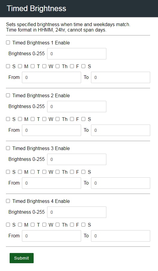
- PWM brightness adjustment including user controlled timed dimming (v0.92 BETA2)
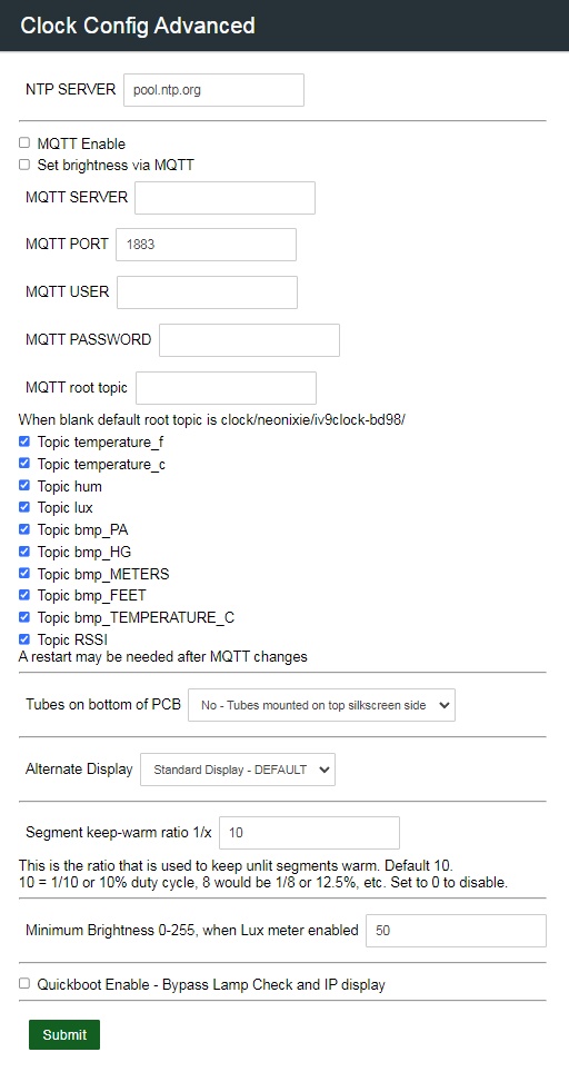
- LUX meter brightness adjustment, optional module
- Digit cross fading (v0.92 BETA2)
- Temperture / humidity display, optional module
- Date display
- Selectable 12/24 hour display with leading zero blanking options
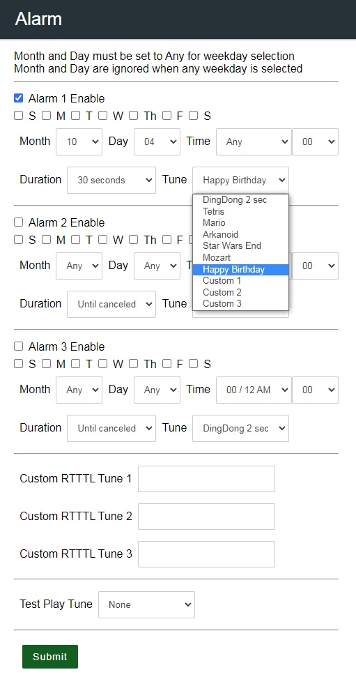
- Alarm feature (using an optional user installed piezo/speaker element) with music capabilities using RTTTL ringtones (v0.92 BETA2)
- Alternate display options: Altimeter (with optional BMP280 sensor), RSSI, LUX (with optional AHT20 sensor)
- MQTT client to publish sensor data and set clock brightness (v0.92 BETA2)
- Cathode Poisoning Prevention options
Back to Table of Contents
More technical details
The clock uses the following ESP32 pins as provided by the original ESP32-DevKitC-VE board.
- 3.3v
- Ground (between GPIO pins 12 and 13)
- 5.0v
- GPIO 19 HV5x22 IC, OUTPUT ENABLE
- GPIO 18 HV5x22 IC, CLOCK
- GPIO 4 HV5x22 IC, DATA
- GPIO 22 and 21 for SCL and SDA (Optional I2C devices)
The ESP32-DevKitC-VE board has a row spacing of 1.0", similar clone boards MAY be able to be used if specs and pinouts match. We highly recommend using an original ESP32-DevKitC-VE board.
The clock uses the following Raspberry Pi pins.
- 5.0v power Physical pin 2
- Ground Physical pin 39
- 3.3v power output Physical pin 1
- HV5x22 IC, OUTPUT ENABLE Physical pin 35, GPIO 19 (Hardware PWM1)
- HV5x22 IC, CLOCK Physical pin 24, GPIO 08
- HV5x22 IC, DATA Physical pin 16, GPIO 23
- SCL and SDA (Optional I2C) Physical pin 3 and 2, GPIO 03 and GPIO 02
Back to Table of Contents